33 Modeling crosstalk from SQUID design
LiteBIRD, Crosstalk, Systematics, Detectors and readout, Research software
33 Modeling crosstalk from SQUID design
33.1 Introduction
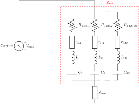
Montgomery et al.1 developed a theoretical model describing how the SQUID design generates the crosstalk matrix, and should be valid for digital frequency-domain multiplexing (DfMUX) with Digital Active Nulling (DAN), and is validated using SPT-3G data. See fig. 33.1 for the circuit model.
33.2 The crosstalk model and an exact solution
Montgomery et al.3 makes use of 3 approximations, 2 mathematical and 1 computational,
- Eq. 3 approximates the total (network) impedance by that at a leg, used in leakage power crosstalk;
- Sec. 3.2 approximates the phase of the total signal by that of the detector signal; and
- an implicit assumption in software that solves for resonance frequencies by finding extrema on a grid.
Here, the same model is used without these 3 approximations.
This is released in the util module in open-source library coscon which stands for Cosmological Convenient functions. The total_crosstalk_matrix function implements the model Montgomery2020 in Montgomery et al.4 whereas the total_crosstalk_matrix_exact function implements the same model without the 3 approximations, named Montgomery2020Exact here.
33.3 Comparison
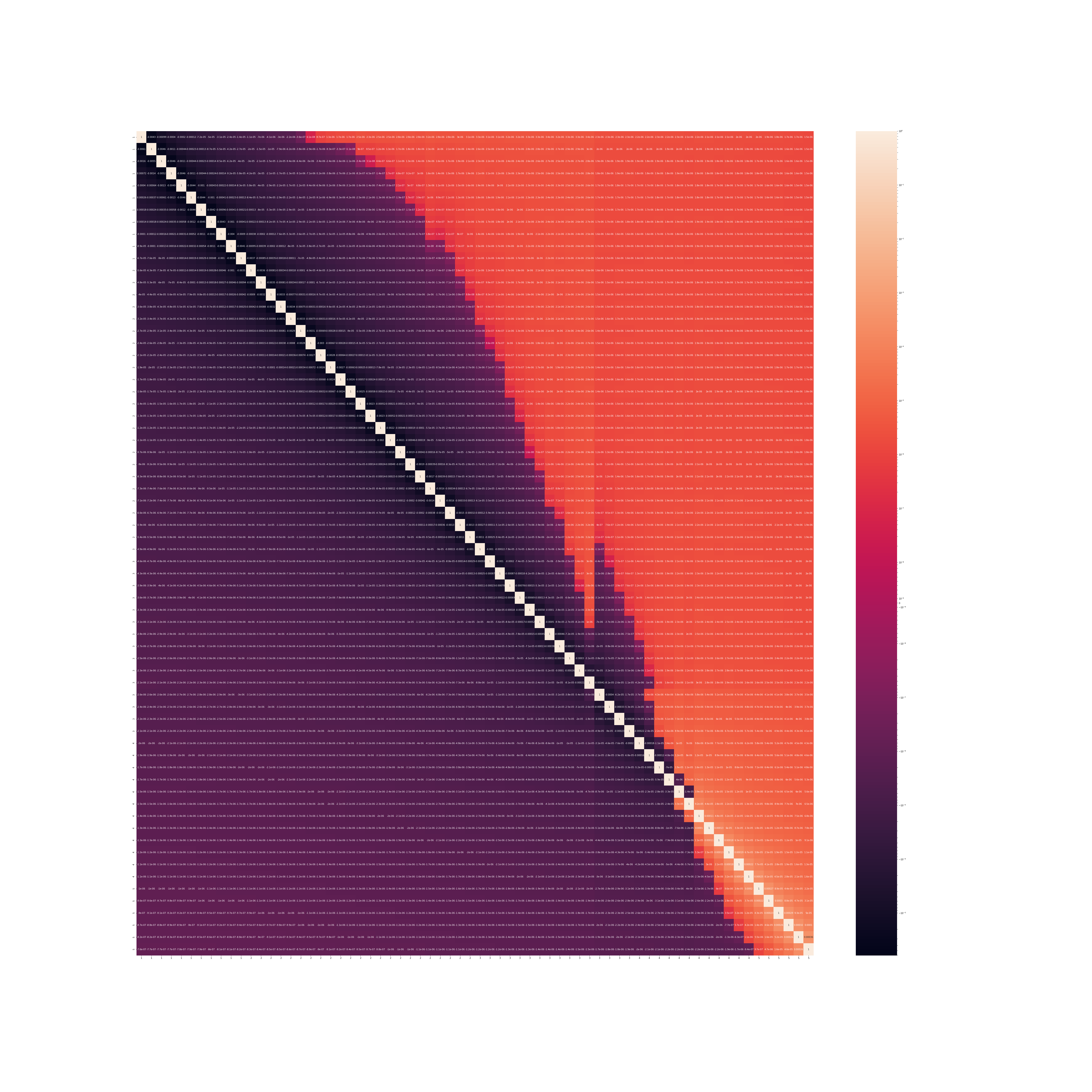
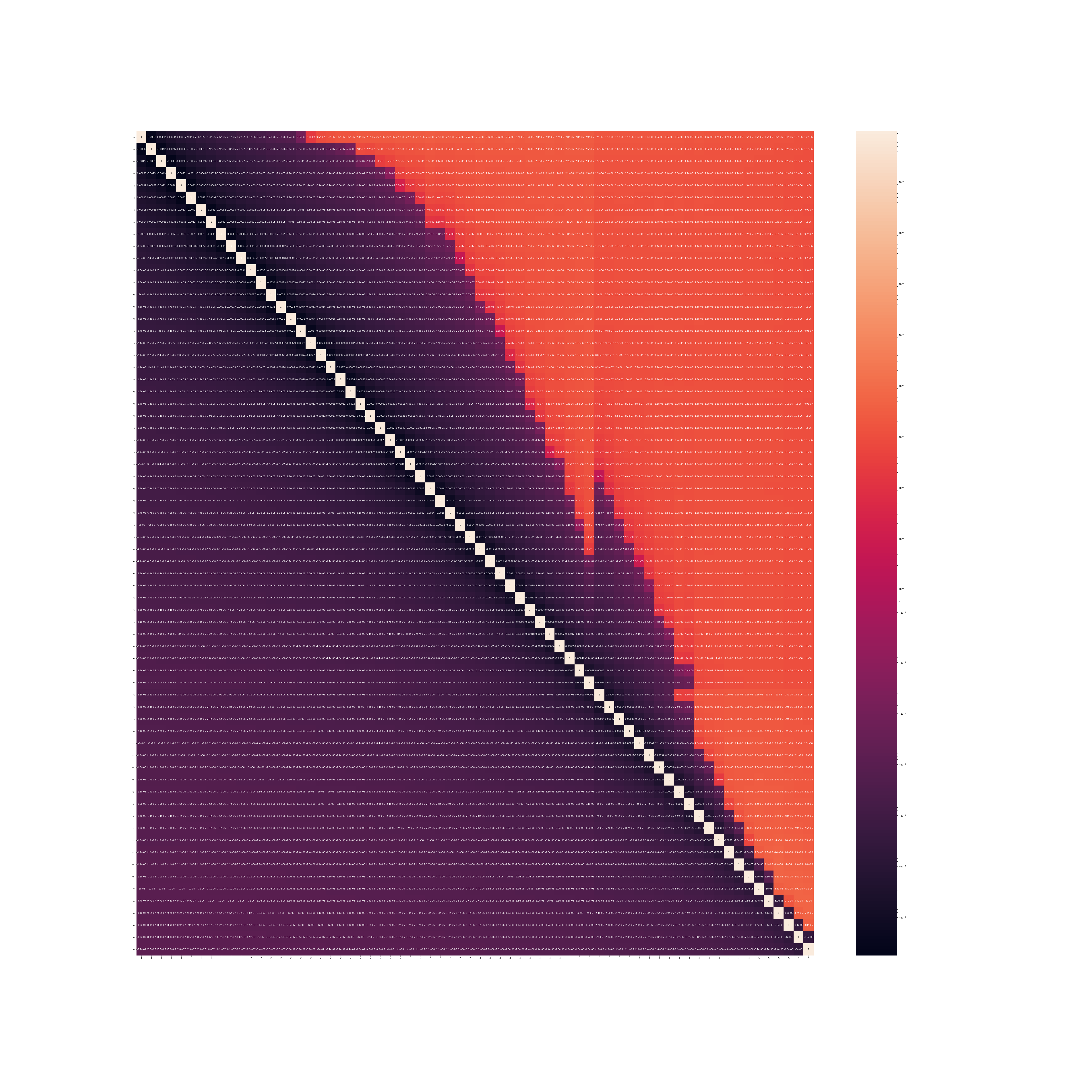
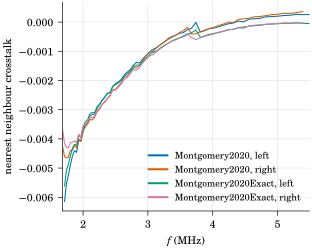
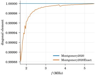
Figure 33.2: Comparison between Montgomery2020 and Montgomery2020Exact models.
Using the same internal SPT-3G SQUID parameters as that in Montgomery et al.5 the crosstalk matrices using Montgomery2020 and Montgomery2020Exact models are compared in fig. 33.2.
These are tiny corrections and the experimental variations are much bigger.6 The result from the Montgomery2020Exact model does have a few minor but interesting features:
- all nearest neighbors have negative crosstalk in this specific example.
- the diagonal is no longer exactly 1, with correction peaked on the order of the crosstalk strength \(\sim {0.01\,\%}\) which is negligible. This correction originates from not using approximation (2). The change of phase contributed by crosstalk will change the magnitude slightly. In practice, the true sensitivity at calibration is measured with this contribution baked in7.
Footnotes
“Performance and Characterization of the SPT-3G Digital Frequency Multiplexed Readout System Using an Improved Noise and Crosstalk Model”.↩︎
Montgomery et al., “Performance and Characterization of the SPT-3G Digital Frequency Multiplexed Readout System Using an Improved Noise and Crosstalk Model”.↩︎
“Performance and Characterization of the SPT-3G Digital Frequency Multiplexed Readout System Using an Improved Noise and Crosstalk Model”.↩︎
“Performance and Characterization of the SPT-3G Digital Frequency Multiplexed Readout System Using an Improved Noise and Crosstalk Model”.↩︎
“Performance and Characterization of the SPT-3G Digital Frequency Multiplexed Readout System Using an Improved Noise and Crosstalk Model”.↩︎
Montgomery et al., “Performance and Characterization of the SPT-3G Digital Frequency Multiplexed Readout System Using an Improved Noise and Crosstalk Model,” fig. 7.↩︎
So the raw sensitivity should be what is measured divided by this factor.↩︎